

Implantable BCI Object Process Model
iBCI-CC Workgroup: Modular Components, Interoperability, and ISO/Other Standards
Contributors: Rob Franklin & Matt DeNardo
This page includes a system model for Implantable BCI’s. The primary audience for this diagram is developers of BCI systems who are looking to create a system partitioning that is intended to maximize reuse by aligning with the system model described herein. Another audience for this diagram is developers of modules intended to be used with or as part of BCI systems who are seeking to facilitate integration of their module into a system being developed elsewhere.
The model is created using the OPCloud Software (https://www.opcloud.tech/) following the OPM Standard (ISO 19450, see Wikipedia Article for basic info).
Model Summary
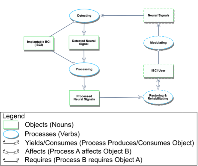
Two views of the model are shown in the attached OPM/OPL diagrams. The first diagram is a simplified version intended to show only the most essential elements of the system and the flow of information through the system. The second diagram is a more complete version of the system showing the flow of information through an iBCI and all required elements that are common to iBCI systems.
The following provides a brief overview of the flow of information, beginning with the iBCI User. The terms in parentheses are omitted from the simplified diagram but can be found in the complete diagram.
An iBCI Usermodulates Neural Signals.
Those Neural Signals are detected by the iBCI.
The Detected Neural Signals are then internally processed by the iBCI into Processed Neural Signals.
The iBCItransmits the Processed Neural Signals externally.
Finally, the iBCI uses the Processed Neural Signals to restore and rehabilitate the iBCI User.
Figure 1: Simplified iBCI Diagram
Full Model
Figure 2: iBCI System Diagram
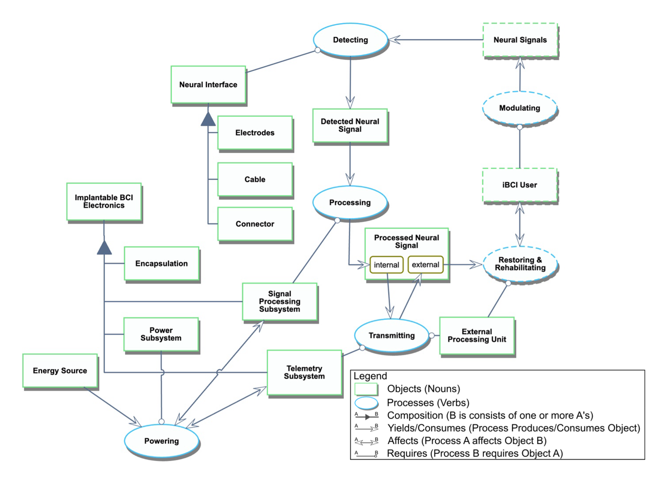
The following describes the relationships between the objects and processes in the diagram using OPM language (ISO 19450).
Object Descriptions
Processed Neural Signal can be external or internal
Neural Interface consists of Electrodes, Cable, and Connector.
Implantable BCI Electronics consists of Encapsulation, Power Subsystem, Signal Processing Subsystem, and Telemetry Subsystem.
Process Descriptions
Detecting requires Neural Interface.
Detecting consumes Neural Signals.
Detecting yields Detected Neural Signal.
Processing requires Signal Processing Subsystem.
Processing consumes Detected Neural Signal.
Processing yields Processed Neural Signal at state internal.
Powering requires Power Subsystem.
Powering affects Signal Processing Subsystem and Telemetry Subsystem.
Powering consumes Energy Source.
Transmitting changes the state of Processed Neural Signal from internal to external.
Transmitting requires External Processing Unit and Telemetry Subsystem.
Restoring & Rehabilitating requires External Processing Unit.
Restoring & Rehabilitating affects iBCI User.
Restoring & Rehabilitating consumes Processed Neural Signal at state external.
Modulating requires iBCI User.
Modulating yields Neural Signals.
For more information on OPM modeling see https://en.wikipedia.org/wiki/Object_Process_Methodology